






NewsCenter
Industrial Baghouse Dust Collector: Key Components and Functions
Author: jiuzhoudust Date: 2026-09-28 18:16:44 Views: 94
Industrial facilities generating airborne dust face a dual challenge: maintaining regulatory compliance and protecting worker health. Whether the source is cement manufacturing, steel production, power generation, or chemical processing, airborne particulate must be captured before it reaches the atmosphere or the shop floor. The baghouse dust collector remains one of the most widely deployed particulate control devices across heavy industry, and for good reason — it handles high dust loads, achieves low emission rates, and accommodates a broad range of particle sizes and gas conditions.
But a baghouse is not a monolithic box. It is an assembly of engineered components, each serving a specific function within the filtration cycle. Buyers who understand these components make better procurement decisions. Operators who understand them troubleshoot faster and avoid costly downtime. This article breaks down every major component of an industrial baghouse dust collector, explains how each works, and highlights what to watch for during selection and maintenance.
What Is a Baghouse Dust Collector?
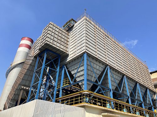
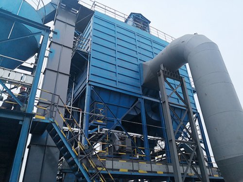
A baghouse dust collector is a dry filtration system that removes particulate matter from industrial gas streams. Dirty air enters the collector, passes through fabric filter bags, and clean air exits through an exhaust stack. Dust captured on the bag surface is periodically dislodged by a cleaning mechanism — most commonly pulse-jet cleaning — and collected in a hopper for removal.
Baghouse systems are classified by their cleaning method: pulse-jet, reverse-air, or shaker. Pulse-jet baghouses dominate modern industrial installations because they allow continuous online cleaning, meaning filtration proceeds without interrupting airflow. This article focuses on pulse-jet baghouse architecture, as it represents the majority of new installations worldwide.
Key Components of a Baghouse Dust Collector
Filter Bags and Cages
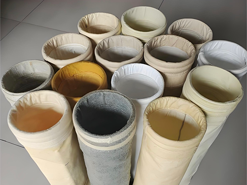
Filter bags are the primary filtration medium. They are tubular fabric sleeves, typically 3 to 6 meters in length, sewn from woven or felted textile media. The fabric material is selected based on the gas temperature, chemical composition, moisture content, and abrasiveness of the dust. Common media include polyester, polypropylene, acrylic, PPS (polyphenylene sulfide), P84, fiberglass, and PTFE (Teflon) laminates.
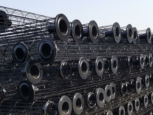
Each bag is supported internally by a metal cage — a cylindrical frame made of galvanized steel, stainless steel, or carbon wire. The cage prevents the bag from collapsing under negative pressure and keeps the fabric taut so that dust forms a filter cake on the outer surface. The cage's wire diameter, ring spacing, and surface finish all affect bag life. Poorly finished cage wires with burrs or sharp edges can tear bags during pulse cleaning, shortening service life significantly.
Bag-to-cage fit is another underappnowledged variable. If the cage is too loose, the bag sags and develops fold lines that wear through. If the cage is too tight, the bag cannot flex during pulse cleaning, which reduces cleaning effectiveness. Manufacturers typically specify a 5 to 15 mm diameter differential between the bag and cage to balance support and flexibility.
Pulse Jet Valve and Compressed Air System
The pulse-jet cleaning system is what distinguishes a pulse-jet baghouse from other designs. It consists of a compressed air reservoir, a series of solenoid-controlled pulse valves, blow pipes with nozzles positioned above each row of bags, and a timer or electronic controller that triggers pulses in sequence.
When a valve fires, it releases a short burst — typically 50 to 200 milliseconds — of compressed air (usually 0.4 to 0.7 MPa) into the top of the filter bag. This creates a reverse pressure wave that travels down the bag, flexing the fabric outward and dislodging the accumulated dust cake. The dust drops into the hopper below.
Pulse valve sizing is critical. Undersized valves produce weak cleaning pulses, leaving dust on the bags and causing pressure drop to climb. Oversized valves waste compressed air and can damage bag fabric over time through excessive flexing. The number of valves per cleaning row, the blow pipe nozzle geometry, and the pulse duration are all engineered to match the bag length, diameter, and dust characteristics.
The compressed air supply must be clean and dry. Moisture in the compressed air can cause bag blinding — a condition where fine particles bond to damp fabric and form an impenetrable layer. Oil contamination from the compressor can similarly coat the bag media and reduce permeability. A properly sized air dryer and filter set upstream of the pulse valve manifold is not optional; it is essential for reliable operation.
Collector Housing and Air Inlet/Outlet
The housing is the structural enclosure that contains the filter bags, cages, and cleaning system. It is typically fabricated from carbon steel with corrosion-resistant coatings, though stainless steel construction is used in corrosive or hygienic applications. The housing must withstand the internal operating pressure (positive or negative) and accommodate thermal expansion if the gas stream is hot.
The air inlet is designed to reduce incoming gas velocity and distribute flow evenly across the filter bags. Many baghouses incorporate a baffle plate or deflector at the inlet to prevent high-velocity gas from directly impinging on the first row of bags, which would cause premature wear. Some designs use a settling chamber or pre-separator section to allow larger particles to drop out before reaching the filter bags, reducing the dust load on the fabric.
The clean air outlet is located on the opposite side or top of the collector, downstream of the filter bags. It may include a clean air plenum that collects filtered air before it exits to the exhaust stack. The outlet is also where continuous emissions monitoring systems (CEMS) are typically installed, measuring opacity or particulate concentration to verify compliance with emission limits.
Dust Hopper and Discharge System
The hopper is the funnel-shaped bottom section of the baghouse where dislodged dust accumulates. Hopper design affects both dust storage capacity and discharge reliability. The hopper walls must be steep enough — typically 60 degrees or steeper from horizontal — to ensure dust flows freely toward the discharge point without bridging or ratholing.
Dust is removed from the hopper by a rotary airlock valve, screw conveyor, or flap valve. The rotary airlock is the most common discharge device in continuous-duty baghouses because it maintains a pressure seal between the hopper (which may be under negative pressure) and the atmosphere while transferring dust out. The clearance between the rotor and housing must be tight enough to prevent air infiltration but not so tight that the rotor binds when dust is present.
Hopper level sensors are installed to detect when dust accumulation exceeds a safe level. If a hopper overfills, dust backs up into the baghouse, blocking the filter bags and causing pressure drop to spike. This is one of the most common causes of unplanned baghouse shutdown.
Fan and Blower Assembly
The induced draft (ID) fan or forced draft (FD) fan provides the motive force that pulls or pushes gas through the baghouse. In most pulse-jet baghouses, the fan is located downstream of the filter bags, pulling clean air through the system under negative pressure. This arrangement keeps the fan handling clean, filtered air, which extends fan life and reduces abrasion on impeller blades.
Fan sizing is one of the most consequential design decisions in a baghouse project. The fan must deliver the required airflow (typically expressed in cubic meters per hour or cubic feet per minute) against the system's total pressure drop, which includes the pressure drop across ductwork, the filter bags, the hopper, and the exhaust stack. The fan curve must be matched to the system resistance curve, and sufficient margin must be built in to accommodate the increase in pressure drop as the filter cake builds between cleaning cycles.
Fan efficiency matters for operating cost. The fan is typically the largest energy consumer in a dust collection system. Variable frequency drives (VFDs) are increasingly standard, allowing fan speed to modulate with actual demand rather than running at full speed constantly.
Pressure Differential Monitoring System
The pressure differential (delta P) across the filter bags is the single most important operating parameter in a baghouse. It is measured by a pressure transmitter installed across the clean and dirty sides of the tube sheet. A normal operating range depends on the application, but typical values fall between 800 and 2000 Pa (3 to 8 inches water gauge).
Rising delta P indicates that the bags are loading with dust and that cleaning is not keeping up. Falling delta P, paradoxically, can also indicate a problem — it may mean bags are developing leaks or that the filter cake has been over-cleaned, allowing fine particles to pass through. The pressure differential trend over time is used to optimize cleaning frequency, adjust pulse duration, and schedule bag replacement.
Modern baghouses use electronic pressure transmitters with digital displays and data logging. Many integrate with plant control systems (DCS or SCADA) to provide real-time monitoring and alarms. A sudden spike in delta P should trigger an investigation into hopper level, compressed air pressure, and pulse valve function.
Control Panel and Automation
The control panel is the nerve center of the baghouse. At minimum, it manages the pulse cleaning sequence — determining which valve row fires, in what order, and at what interval. Older systems used mechanical timers; modern systems use programmable logic controllers (PLCs) that offer far more flexibility.
Advanced PLC-based controls can adjust cleaning parameters based on real-time conditions. For example, if the pressure differential is low, the controller can extend the time between pulses to save compressed air. If delta P rises above a setpoint, the controller can switch to a more aggressive cleaning mode with shorter intervals and longer pulse durations. Some systems also incorporate broken bag detectors — optical or triboelectric sensors that monitor the clean air side for particulate, alerting operators when a bag leak occurs.
The control panel also interfaces with the dust discharge system, managing rotary valve operation and hopper level alarms. In fully automated plants, the baghouse PLC communicates with the central DCS, allowing remote monitoring and integration with broader emissions management strategies.
How Components Work Together
A baghouse operates as an integrated system, not a collection of independent parts. Dirty gas enters through the inlet, where a baffle or pre-separator reduces velocity and drops out large particles. The gas then passes through the filter bags from outside to inside — dust collects on the outer bag surface, forming a filter cake that actually improves filtration efficiency beyond what the bare fabric alone can achieve.
As the cake builds, pressure differential rises. When delta P reaches a preset threshold or a timer interval elapses, the PLC fires a pulse valve. Compressed air blasts into the top of a row of bags, flexing the fabric and fracturing the dust cake. Dislodged dust falls into the hopper, where it awaits discharge through the rotary airlock. The cleaned bags resume filtration, and the cycle continues with the next row.
The fan maintains constant airflow throughout this process, pulling clean air from the plenum to the exhaust stack. The pressure differential transmitter continuously monitors the system, feeding data back to the PLC. If any component in this chain — the bags, cages, valves, hopper, fan, or controls — underperforms, the entire system's efficiency drops.
Common Component Failures and Diagnostics
Bag failures are the most frequent issue. They manifest as elevated stack opacity, declining pressure differential, or visible dust at the clean air outlet. Causes include mechanical wear from cage friction, chemical attack from acid or alkali in the gas stream, thermal degradation from operating above the media's temperature limit, and blinding from moisture or oil. Diagnosing the root cause requires inspecting the failed bag visually and, in persistent cases, sending a sample for laboratory analysis of tensile strength and chemical resistance.
Pulse valve failures typically present as rising pressure differential that does not respond to increased cleaning frequency. A failed solenoid may not open at all, leaving an entire row of bags uncleaned. A leaking pulse valve wastes compressed air continuously and produces a weak pulse. Diagnostic steps include checking the solenoid coil for continuity, inspecting the valve diaphragm for tears, and verifying that the compressed air supply maintains adequate pressure during firing.
Hopper discharge failures are insidious because they develop gradually. A rotary airlock with worn vanes allows increasing air infiltration, which disrupts dust flow and can actually lift dust back into the baghouse. Bridging — where dust forms an arch over the discharge opening — is common in fine, cohesive dusts. Installing a bin vibrator or acoustic horn on the hopper can prevent bridging, but these are corrective measures, not substitutes for proper hopper geometry.
Fan problems usually relate to bearing wear, impeller imbalance from dust accumulation, or vibration from structural resonance. Regular vibration analysis and bearing temperature monitoring catch these issues before they lead to catastrophic failure.
Selecting the Right Components for Your Application
Component selection starts with a clear definition of the process conditions: gas volume, temperature, dust loading (concentration), particle size distribution, chemical composition of the gas and dust, and moisture content. These parameters drive every subsequent decision.
Filter media selection is the most consequential. A polyester felt bag is suitable for dry, mildly acidic gas below 130°C. For gas streams containing sulfur compounds or operating above 180°C, PPS or fiberglass media becomes necessary. For abrasive dusts like silica or metal fines, a singed or expanded-PTFE membrane surface treatment extends bag life. The cost difference between standard polyester and high-performance media is significant, but premature bag failure on an aggressive application costs far more in downtime and production loss.
Cage material should match the corrosion environment. Galvanized steel cages are adequate for dry, non-corrosive applications. Stainless steel (304 or 316L) is specified when the gas stream contains acidic moisture or when the facility operates in a coastal environment. For extreme corrosion or high-temperature service, epoxy-coated or special alloy cages may be required.
Hopper capacity should be sized based on the dust generation rate and the discharge frequency. A hopper that is too small requires continuous discharge, which increases the risk of air infiltration through the rotary valve. A hopper that is too large adds unnecessary height and cost. Most designs target a residence time of 2 to 8 hours of dust accumulation at full load.
Fan selection should account for future expansion. Installing a fan with a 15 to 20 percent airflow margin allows for production increases without requiring a fan replacement. The motor should be sized to handle the maximum pressure drop condition, which occurs when bags are at their dirtiest just before a cleaning cycle.
Maintenance Best Practices
Effective baghouse maintenance is predictive, not reactive. The foundation is a consistent data collection routine: log pressure differential, compressed air pressure, pulse valve cycle count, hopper level, and stack opacity daily. Trends in these parameters reveal developing problems long before they cause a shutdown.
Bag inspection should occur at scheduled intervals — typically every 6 to 12 months depending on duty. Inspect for hardening, embrittlement, chemical attack, mechanical wear, and pinhole leaks. Replace bags proactively when they show signs of approaching end of life, not after they fail. A planned bag changeout during a scheduled outage costs a fraction of an emergency changeout during production.
Pulse valve maintenance is straightforward but often neglected. Inspect diaphragms annually for cracking and replace as needed. Clean the compressed air filter regularly — a clogged air filter reduces pulse pressure and causes weak cleaning. Verify that the solenoid valves are firing correctly by listening for the characteristic "pop" during each pulse, or use an electrical test at the PLC output.
Hopper maintenance focuses on the discharge system. Check rotary valve clearances periodically and adjust or replace the rotor seal as wear develops. Clean dust buildup from the hopper walls during outages. Verify that level sensors are functional and calibrated.
For the fan, follow the bearing manufacturer's lubrication schedule. Conduct vibration analysis quarterly. Inspect impeller blades for erosion or dust buildup, and clean as needed. Check fan belts (if belt-driven) for tension and wear.
Frequently Asked Questions
How often should filter bags be replaced in an industrial baghouse?
Bag life varies widely by application. In favorable conditions — moderate temperature, non-abrasive dust, proper cleaning — bags may last 3 to 5 years. In aggressive environments with high temperature, acidic gas, or abrasive dust, bag life may be 12 to 18 months. Monitoring pressure differential trends and conducting regular visual inspections provides the most reliable basis for replacement timing.
What pressure differential indicates a problem with the baghouse?
Every baghouse has a characteristic operating range. A sudden spike above the normal range suggests cleaning system failure, hopper overfilling, or excessive dust loading. A gradual upward trend indicates bags are blinding or approaching end of life. A drop below the normal range may signal bag leaks or over-cleaning. Baseline the system during commissioning and track deviations from that baseline.
Can a pulse-jet baghouse operate with moisture in the gas stream?
Pulse-jet baghouses can handle moisture if the gas temperature remains above the dew point throughout the system. If the gas drops below dew point, moisture condenses on the bags, causing blinding and potential chemical corrosion. In applications with moisture risk, insulating the housing and maintaining gas temperature above dew point by a margin of 15 to 20°C is standard practice.
What is the difference between online and offline pulse-jet cleaning?
Online cleaning occurs while the baghouse remains in operation — airflow continues as individual rows are pulsed sequentially. This is the standard mode for most pulse-jet baghouses. Offline cleaning involves isolating a compartment (closing an inlet damper) before pulsing, then returning it to service. Offline cleaning is used in multi-compartment baghouses for applications where online cleaning is ineffective, such as very fine or sticky dusts.
How is baghouse filtration efficiency measured?
Filtration efficiency is typically expressed as the percentage of particulate removed from the gas stream, or as an emission concentration (mg/m³ or grains/ft³). It is measured by stack testing — either through EPA Method 5 (particulate sampling) or through continuous opacity monitoring. A well-maintained baghouse with intact bags typically achieves emission rates well below 10 mg/m³.
Conclusion
An industrial baghouse dust collector is a system of interdependent components, each engineered for a specific role in the filtration process. Understanding the filter bags and cages, the pulse-jet cleaning system, the housing and flow distribution, the hopper and discharge, the fan, the pressure monitoring, and the control panel gives engineers and procurement teams the foundation to specify, operate, and maintain these systems effectively. Component selection should always be driven by the actual process conditions — gas properties, dust characteristics, and operating parameters — rather than by generic recommendations. With proper selection and disciplined maintenance, a baghouse delivers reliable, low-emission performance across decades of industrial service.
References
EPA, "OAQPS Control Cost Manual, Chapter 9: Fabric Filters," U.S. Environmental Protection Agency, Office of Air Quality Planning and Standards.
OSHA, "Occupational Exposure to Respirable Crystalline Silica," OSHA Technical Manual, Section III, Chapter 1.
NFPA 68, "Standard on Explosion Protection by Deflagration Venting," National Fire Protection Association.
ASHRAE Handbook — HVAC Applications, Chapter 33: Industrial Exhaust Systems, American Society of Heating, Refrigerating and Air-Conditioning Engineers.
NFPA 654, "Standard for the Prevention of Fire and Dust Explosions from the Manufacturing, Processing, and Handling of Combustible Particulate Solids," National Fire Protection Association.
 Recommended Products
 Contact Us
—— Consultation Hotline: +86 17331708686
—— WhatsApp:+8617331708686
—— Email: lujingya66@163.com
—— Website:https://www.jiuzhoudust.com
—— Address: Siying Development Zone, Botou City, Hebei Province, China